Online tools are helping engineers
Linear technology plays a key role in the automation of production processes, which requires powerful solutions that meet the growing requirements in terms of efficiency, reliability, carrying capacity and precision. Configuring these often very complex systems calls for in-depth expert knowledge. Online tools simplify the entire process – from designing linear units right through to commissioning them – and offer engineers extremely valuable assistance as they carry out their work. When coupled with the right software, strong automation solutions for multi-axis gantries and pick-and-place tasks can be implemented quickly and conveniently. Synchronised linear units are often the perfect choice when it comes to implementing applications that require carriages or overhangs to move in parallel.
When it comes to process automation, various requirements are placed on linear units. Speed, payload, precision, stroke length, reliability and robustness, along with other factors such as area of application and duty cycle, all play a decisive role with regard to selecting and designing linear units and guides, drive elements, motors, control systems and the relevant accessories. Finding the right linear unit with the suitable drive components is therefore a complex and time-consuming task for engineers – and digitalisation is becoming increasingly important in this regard. Online tools offer engineers just the support they need when selecting, designing and configuring mechanical components and systems. They provide engineers with an application-specific solution for their transport task in next to no time.
Using synchronised linear units
Some applications call for linear units to be arranged in parallel to one another if, for example, both units have to move in sync on a single level. One option for implementing this on a technical level would be to equip each linear unit with its own drive and install a PLC to regulate the entire synchronisation process. However, it would be easier and more cost-effective to connect the linear units via a shaft and use a single motor. That said, this makes the design process more complex, as it also means finding suitable couplings and drive shafts for the chosen linear units in addition to drive components. Not only that, but engineers also have to determine the torque load during acceleration and braking manoeuvres. “Thanks to item MotionDesigner®, automation couldn’t be easier”, says Uwe Schmitz, product management team leader for item linear motion units® at item Industrietechnik GmbH. “A whole host of different automation tasks can be covered by a single online tool, perfectly tailored to the particular mechanical and electrical requirements.” Mechanically synchronised Linear Units can be easily tailored to the transport task at hand using item MotionDesigner®. The intelligent program determines the perfect combination of two Linear Units and one Synchroniser Shaft to enable two carriages or two Linear Units to be moved in parallel. “The item building kit system offers ready-made solutions for a wide range of Linear Units – the item Synchronising Sets,” Schmitz explains. “These sets comprise Couplings that are fitted between two Linear Units and are connected by a Synchroniser Shaft.” These Couplings are perfectly configured to the Linear Units. Two metallic claws encompass a plastic Coupling Insert that compensates for axial and radial offset. Another advantage of this Coupling is that it cushions rotary movements. What’s more, it can withstand the relevant torques over the long term.
Using Linear Units for gantry solutions
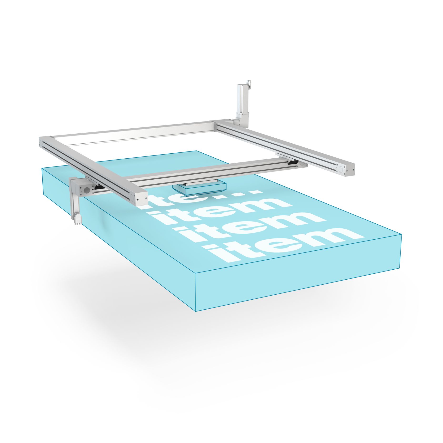
When it comes to automating production processes with parallel Linear Units, there is a wide range of possible gantry solutions. These are combinations of Linear Units that can be used for numerous tasks – such as controlling different points on a given level with a single tool – whereby two axes run in parallel and are connected by a Synchroniser Shaft. These 2D gantries are used in systems designed to print or inspect surfaces, for example. This involves tools such as (push-)buttons and sensors being moved over a wide range with the utmost precision. There are also many excellent linear axis combinations available for 3D gantries to carry out demanding positioning tasks in three dimensions. Synchronised Linear Units can be used to construct numerous pick-and-place systems, for example, with grippers and tools for the processing tasks fitted to the carriages and support profiles.
A complex task with a high potential for error
When designing synchronised linear axes, there are many influencing factors that engineers need to take into account. The mounting position, dynamic parameters and any loads or forces exerted on the structure all play a key role. The length of the Synchroniser Shaft must be set in accordance with the maximum possible speed. Datasheets can be used as a basis for calculating torques and selecting Couplings. To achieve a system that runs perfectly, it must also be possible to mechanically combine the selected components. Engineers are thus faced with a highly complex task that demands both extensive expert knowledge and a great deal of time. “Linear Units are often designed on the basis of relevant key parameters and somewhat oversized for safety reasons,” explains Schmitz. “But larger dimensions mean higher costs.” However, if the system is not of an adequate size, this will result in defects, downtime and inefficient processes. If dimensions do not match the screw connections or fittings, or the individual components are not compatible, this will lead to additional outlay further down the line, as errors will have to be rectified by means of subsequent machining.
The best possible support for designing
Systems with perfectly designed Linear Units can deliver optimum speed, precision and load-carrying capacity, and run efficiently over the long term. The item online tool simplifies the process of dimensioning and selecting components. “item Motion Designer® calculates the maximum torques, for example, and suggests a solution with a suitable Coupling,” says Schmitz. “The intelligent program also recognises the relationship between the length of the Synchroniser Shaft and the maximum speed of the synchronised linear axes.” item MotionDesigner® calculates the necessary length of the Synchroniser Shaft and the dimensions of a housing, if required. Since the load can be distributed unevenly between both carriages on synchronised Linear Units, the program provides a detailed depiction of the forces generated and takes into account the torque load during acceleration and braking manoeuvres. The software’s comparison function enables users to see both the technical requirements defined by the data they input and the technical specifications for the system recommended by item. Engineers can choose between the system that matches their exact requirements and alternatives that offer larger power reserves. item therefore significantly automates and simplifies the process of specifying systems and provides an ideally dimensioned turnkey solution including Synchronising Set, Motor, Gearbox and Controller. The design software automatically creates a complete set of documentation with all the technical details and CAD data. In addition, engineers can draw on numerous example applications including the construction data that item provides.
Simplified commissioning
The data generated during the design process is immediately made available when the Linear Units are commissioned using item MotionSoft®. The software automatically determines the best possible controller settings and checks the coordination of the parallel Linear Units in a test run, meaning a system made of synchronised Linear Units can be up and running in just a few minutes. An online help system, meanwhile, provides users with comprehensive support and specific answers to any questions they might have about parametrisation and commissioning.
Length: 8,583 characters including spaces
Date: 27 April 2020
Photos: 3
Caption 1: 2D gantries in systems designed to print or inspect surfaces can be implemented quickly and easily using item components. Source: item
Caption 2: There are many excellent linear axis combinations available for 3D gantries to carry out demanding positioning tasks in three dimensions. Source: item
Caption 3: item MotionSoft® commissioning software automatically determines the best possible controller settings for mechanically synchronised Linear Units. Source: item